CEA started developing energy storage services in 2015, at a relatively early stage in the storage industry. The company foresaw the growth potential of stationary energy storage as a critical enabler of the renewable energy transition and a valuable asset for grid operators.
In the last eight years we have seen battery cells scaling from below 100 Ah to today’s 300-plus Ah; systems transforming from 12-meter, walk-in containers to today’s highly integrated, energy-dense modular cabinets; and the advent of liquid-cooled systems necessitated by big cells.
Battery suppliers have created specialized cell formats and chemistries for the stationary BESS sector, versus using electric vehicle cells in grid storage systems, as in the early days. We have also witnessed the transition of BESS’ from a nickel, cobalt, and manganese (NCM) battery cell chemistry – mainly supplied by South Korean and Japanese manufacturers – to lithium ferrous phosphate (LFP) devices, exclusively supplied by Chinese manufacturers. Other storage technologies, such as flow batteries, have yet to make a breakthrough and take a slice of the market from lithium-ion batteries (LIBs).
Rapid change
Overall, the industry is very different from a few years ago. This has brought significant challenges, exacerbated by a high growth rate. LIB chemistries have inherent limitations and violating them can lead to excessive degradation that almost invariably results in uncontrolled thermal runaway.
Manufacturing defects, as well as electrical, thermal, or mechanical abuses, can push battery cells into thermal runaway. In the best-case scenario, safety systems will prevent propagation of a fire, leading to the incapacitation of only part of a system. A worst-case scenario could see several containers burn, resulting in lengthy system downtime. Moreover, the complexity found in various subsystems creates additional points of failure that can lead to cell abuse and thermal runaway. A battery fire is the nightmare scenario that any BESS owner or operator wants to avoid at all costs, as it leads to significant reputational and financial damage and lengthy operational disruption.
CEA has been focusing on efficiently identifying the manufacturing risks associated with all levels of an energy storage system, through our quality assurance services. This work includes identifying risks across cell, module, rack, and containerized systems.
Quality in numbers
Since 2018, CEA’s team of engineers has been conducting quality assurance inspections across more than 26 GWh of lithium-ion energy storage projects deployed worldwide. Our quality assurance inspections are performed before production, at pre-production factory audits; during production, through in-line production monitoring; and after production via pre-shipment inspection and factory acceptance testing. More than 1,300 findings have been identified during CEA’s oversight at 52 factories globally. In this context, a finding is an issue identified during inspection that indicates deviation from standard best practice, process deviations, or product specifications.
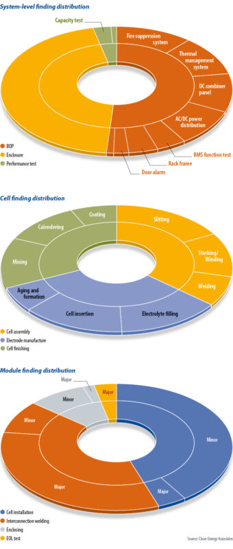
Most industry newcomers overly focus on cell quality and don’t pay close enough attention to integration issues as cells are packaged into modules, racks, and containers. System level issues account for 47% of those identified, compared to 30% at the cell level and 23% at the module level. A battery cell’s complex manufacturing process, and high-performance sensitivity with respect to the robustness of the quality control system, make it the single-most risk-prone component within a BESS. But there are so many other components included in a containerized system that most risks come from the non-cell portions of the BESS. The large number of system-level findings is due to inadequate quality control of highly manual integration processes, the complex nature of energy storage systems, and system vulnerability to underlying problems originating from upstream components such as balance-of-plant (BOP) items and batteries. As the last step of the BESS manufacturing process, system integration can amplify underlying issues at sub-system levels and is vulnerable to additional quality and performance risks at the interfaces between sub-systems.
System-level problems
In integration factories, energy storage systems are built with many moving parts, a fact reflected by the large number of CEA findings on system enclosures – amounting to 45% of the total system-level findings (see chart to the left). However, the majority (84%) of the enclosure findings are minor and pose relatively low risk to system performance and safety. Enclosure inspection comprises visual inspection of appearance, strength and rigidity, wiring and cabling, grounding mechanism, and ingress performance.
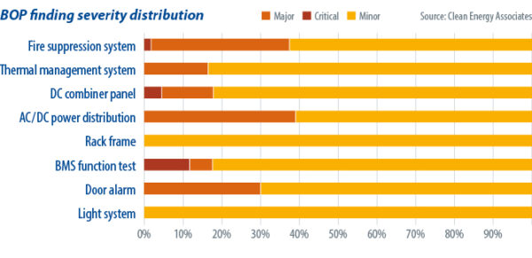
The supporting components and system that form the BOP for a BESS consists of a fire detection and suppression system, a power distribution set-up and a thermal management system. A BESS is inherently vulnerable to defects originating from all upstream components and this is attested by the large number of direct findings in the BOP. The findings in sub-systems are typically caused by sub-component defects and bad practice during system integration. Representative findings include liquid coolant leakage due to deformed flange plates, malfunctioning gas sensors, ventilation failure due to incorrect installation, and live conductor exposure within AC/DC distribution.
Performance test findings contribute only 4% to the total number of system-level findings as capacity and round-trip efficiency (RTE) tests are procedurally straightforward and have explicit pass and fail criteria. In the worst cases, where a system fails both capacity and RTE tests, only two findings will be recorded. However, performance test findings indicate high risk as they are directly linked to system performance guarantees, and the root causes of any failed test usually point to a larger and deeper problem upstream.
Baseline performance tests are crucial to identifying system deficiencies, confirming contractually-promised metrics, and offering one last opportunity to rectify quality and performance issues. Between the two performance tests, a higher percentage of major and critical issues are found during the RTE test, which measures DC system cycling efficiency, excluding auxiliary loads. This is the most challenging test that shows how efficiently batteries have been assembled electrically. Capacity tests are at a more fundamental level and the risk of capacity shortfalls are usually hedged by an implicit rule in battery cell design – that is, to oversize capacity by around 5% at the cell level.
Underachieving system efficiency and capacity is often due to either batteries or BOP systems. The more common findings include underachieving capacity and RTE, resulting from abnormally large temperature and voltage variations among cells within a battery module; charging or discharging failure due to wiring issues in a battery rack’s high voltage boxes; and thermal runaway initiated in one of the battery modules by internal short circuiting.


Cells and modules
Battery-related findings are identified at cell and module factories during the manufacturing and integration processes of the respective components.
The cell is where the electrochemical reactions take place at a nanoscale. Rigorous process control is required to avoid internal short circuiting caused by quality issues. The lengthy manufacturing process and high sensitivity to the storage, packaging, and shipping conditions of battery cells leads to a larger number of findings, compared with battery modules.
The overall cell manufacturing process can be divided into three stages: electrode manufacturing, cell assembly, and cell finishing. Cell assembly processes contain a larger number of findings with higher severity due to their close causal relationship with internal short circuiting. As battery cells evolve to 300 Ah, or even higher capacity levels, it is expected the associated risks will be aggravated due to higher requirements for burr size and foreign particle control during the cell assembly processes.
Similar to the system integration process, battery modules involve highly manual production processes including cell installation, interconnection welding, enclosing, and end of line testing. Cell installation and interconnection welding are responsible for 86% of all battery module-related findings.
Battery cell installation starts with polarity verification, with the cells then placed into brackets that have thermal insulation layers applied in between. Interconnection welding connects cells electrically into the designed configuration. The large number of findings in these two areas is mainly due to imprecision in material handling and welding quality control. Regarding the interconnection welding process, the majority of such findings are major and are caused by poorly defined welding procedures and sloppy operations.
Reducing risk
The rapid pace of battery technology advancement means new risks are being introduced across the supply chain. Accordingly, a multi-stage quality control approach should start from risk assessment at the early stages of the procurement process.
The assessment should identify specific risks associated with project design and use cases, which should inform battery requirements. During production, quality assurance should be executed under close scrutiny to ensure all previously identified risks are covered.
One key takeaway from our 26-plus GWh quality assurance track record is that sometimes even perfect system test results cannot guarantee ongoing performance and reliability once systems are put into operation. Any given energy storage system is only as good as the pass criteria outlined in the supplier’s quality control checklist. We have seen performance test failures due to testing equipment limitations, round-trip efficiency targets that are set too low and do not conform to performance guarantees, temperature and voltage variations that are not monitored and analyzed, untested battery management system control functions, and more. Some of these problems can be addressed in the early procurement stage by conducting a gap analysis of a supplier’s quality assurance and testing protocols.
Ensuring the reliability and performance of BESS’ requires a continual process of reassessment. There should be frequent updates to quality-inspection best practice, risk tracking, and prioritization and development of mitigation approaches. The prize for buyers adhering to a multi-stage quality assurance approach is a safe battery system that performs as expected.
 About the authors: George Touloupas is the senior director of technology and quality for solar and storage at CEA. He has more than 12 years’ experience in technical consulting for PV manufacturing, project development, and solar and energy storage projects.
 Chi Zhang is a senior engineer at CEA. His research focuses on energy storage and green hydrogen.
This content is protected by copyright and may not be reused. If you want to cooperate with us and would like to reuse some of our content, please contact: editors@pv-magazine.com.


If utilities are smart…they WON’T pick a storage system that requires fire suppression, cooling systems or complicated BMS systems. In short, pick a non-lithium battery that is safer, cheaper and made from abundant materials…along with a long cycle life (some of the flow batteries, zinc air, iron air, Ambri, etc, etc.)