 Horizontal single-row solar trackers can deliver higher value at lower cost by increasing the available options regarding tracker length.
The ability to drive up to 240 square meters of modules from a single, reliable drive and controller can reduce tracker cost, installation cost, and operations and maintenance cost, and can increase Ground Coverage Ratio (GCR) – the ratio of module area to site area.
While costs are reduced, some challenges are introduced, including the ability to follow terrain, and the ability to track the sun accurately. These challenges and their solutions are discussed in the new white paper developed by OMCO Solar, “Advantages and challenges of single-row trackers up to 120 meters long for utility-scale PV systems.”
Download the white paper
Content includes:
- Analysis of single-row horizontal single-axis trackers
- String sizing, tracker lengths and configurations
- Impacts on Ground Coverage Ratio
- Economic impacts of longer trackers
- Challenges and solutions pertaining to long trackers
- Considerations of terrain, targeting, balance, bearings, and algorithms for longer trackers
Advantages and Challenges of Single-Row Trackers Up To 120 Meters Long For Utility-Scale Photovoltaic Systems
Abstract
Horizontal single-row solar trackers can deliver higher value at lower cost by increasing the available options regarding tracker length.
The ability to drive up to 240 square meters of modules from a single, reliable drive and controller can reduce tracker cost, installation cost, and operations and maintenance cost, and can increase Ground Coverage Ratio (GCR) – the ratio of module area to site area.
While costs are reduced, some challenges are introduced, including the ability to follow terrain, and the ability to track the sun accurately. These challenges and their solutions are discussed below.
OMCO Origin Trackers achieve low total system cost and high GCR by enabling mounting of up to 120 standard 2 meter x 1 meter crystalline silicon modules per tracker.
Background
Utility-scale photovoltaic systems are designed to maximize reliability and minimize life-cycle cost.
Key financial metrics include Levelized Cost of Energy (LCOE), Return on Investment (ROI), Internal Rate of Return (IRR) and Net Present Value (NPV) of the solar power plant.
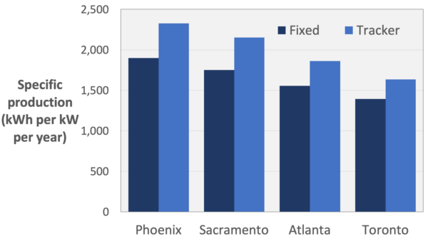
High specific production (kWh per kW per year) is a strong factor toward improvement of these metrics.
In the United States, utility scale projects increasingly use horizontal single-axis trackers, because they have higher specific production than fixed rack systems in most areas of the US. (See Figures 1 and 2.)
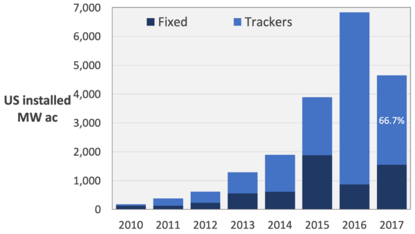
Time-of-use electric rates also reward the use of trackers, since rates are usually higher late in the day, when tracker kWh production is much higher than fixed rack kWh production.
Among horizontal single-axis trackers, single-row trackers are often preferred over multi-row trackers because they offer good access for cleaning. Without regular cleaning, dust accumulation can cause significant losses to specific production in some regions. (Figure 3.)
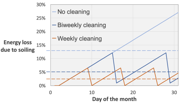
This paper relates to single-row horizontal single-axis trackers.
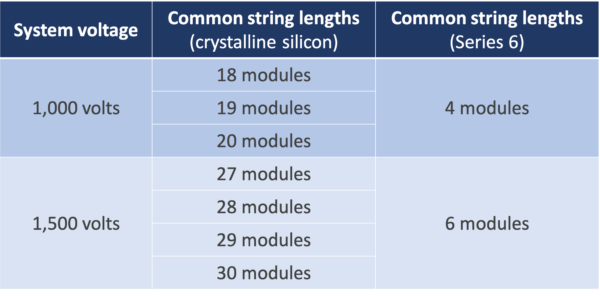
To optimize LCOE, it is generally desired to populate a tracker with a number of whole strings, so as to minimize the need to connect adjacent trackers by dc wiring.
Common string lengths are given in Figure 4.
Reasoning behind tracker lengths up to 120 meters
Ideally a tracker can be designed to accommodate as many whole strings as possible, for a given system voltage, type of module, type of inverter, and climate.
In the late 2000s and early 2010s, the most common maximum length for single-row trackers was approximately 60 meters – long enough to mount up to 60 crystalline silicon modules, about 2 meters long and 1 meter wide.
Some of these trackers are still available, and they can accommodate three strings of 18, 19 or 20 crystalline silicon modules; or two strings of 27, 28, 29 or 30 crystalline silicon modules.
In the mid 2010s, some manufacturers introduced trackers about 90 meters long. These trackers can hold up to five strings of 18 crystalline silicon modules; four strings of 19 or 20; or three strings of 27, 28, 29 or 30.
A tracker length of about 120 meters enables all the string configurations shown in Figure 5.
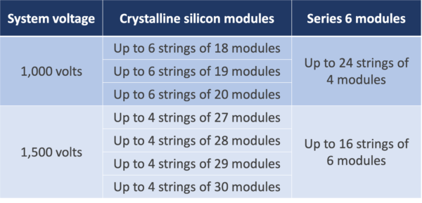
OMCO Origin trackers can mount up to 120 crystalline silicon modules of length about 2 meters and width about 1 meter.
Impact on Ground Coverage Ratio
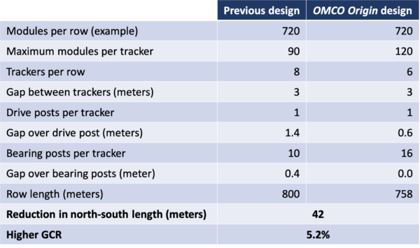
The ability to provide trackers in lengths up to 120 meters, along with other design improvements, can increase GCR in the north-south dimension. (See Figures 6a and 6b.)
Increased GCR means reduced cost per MW for trenching, cabling, site maintenance such as weed removal, and land cost.


Figure 6a shows a common single-row tracker configuration:
- Maximum length approximately 90 meters
- Gap over the center post, where the drive is mounted, about 1.3 meters n Gap over other posts about 0.4 meter
Figure 6b shows the higher-GCR OMCO Origin design:
- Maximum length about 120 meters
- Gap over center post about 0.7 meter n No gap over other posts
This design reduces north-south dimensions for a given number of modules by an average of 5.2% compared with the previous design – details given in Figure 7.
In addition, designers are given more combinations of tracker lengths, so for sites with a given north-south dimension, lots can often be more fully filled.
Figure 8 shows this effect for lots with north-south dimensions up to 600 meters – trackers which enable mounting of any number of modules up to 120 can better fill lots of many north-south dimensions.

An example is given in Figures 9a and 9b.
Both layouts enable mounting of 7,176 crystalline silicon modules about 2 meters long and 1 meter wide.
The first layout requires 123 trackers, and the second requires only 87 trackers – 30% fewer; this reduces LCOE by using fewer controllers and drives, reducing commissioning cost, requiring fewer spare parts, and reducing operations and maintenance cost.
The second layout also allows a single wide east-west aisle compared with two narrow aisles in the first layout.
Economic Impact
This paper will not attempt to quantify all the cost savings associated with longer trackers, but only to identify significant potential savings.
Costs associated with GCR
Figure 6 above suggests that longer trackers, with no gaps over bearings posts, can improve GCR by as much as 5.2%.
On a large site, this may mean less land is needed for a given array size, reducing the cost of land acquisition and maintenance; trenching runs and cable runs may be shorter and thus less expensive; or, alternately, more modules may be put on a given site, increasing kWh production accordingly.
All these changes will improve project performance in terms of LCOE, ROI, IRR, and NPV.
Costs associated with the number of trackers
Trackers powered by slew drives typically require one slew drive per tracker, one motor per tracker, and one control channel per tracker; reducing the number of trackers reduces the number of these components required for a site, and thus the total cost of the photovoltaic power plant.
Reducing the number of trackers needed, by increasing the number of modules per tracker, reduces the total cost of the drive system; the cost to install slew drives, motors and
tracker controllers; the cost to commission trackers; the number of spare parts needed;
and the long-term operations and maintenance cost of the system.
Example
At one site, with string length 24 modules, increasing the number of modules per tracker from 72 to 120 resulted in cost reduction of 3.3 cents per watt.
Challenges and Solutions
Terrain
A long tracker may be less able to accommodate north-south terrain features than a shorter tracker. OMCO Origin trackers can accommodate up to 10% slope north-south.
If the terrain includes peaks or depressions shorter than the optimal length of the tracker, they can be accommodated by changing the layout to use shorter trackers end to end, at minimal added cost. This approach eliminates or minimizes the need for land preparation
such as grading.
Targeting
Long trackers may be more difficult to design for accurate targeting, due to elastic deformation of the structure from the center drive to each end.
A method for evaluating tracking accuracy is given in the IEC standard 628174.
OMCO Origin Trackers incorporate features which make accurate targeting possible with trackers up to 120 meters long.
Balance
When the center of mass of a tracker’s “table” – the structure and modules which move as one – is vertically aligned with the axis of rotation, the tracker is said to be “in balance”.
Trackers which are not in balance may show significant deflections from the middle to each end, since the table will have a bias toward a horizontal or vertical position.
OMCO Origin Trackers are designed to be very tightly in balance when modules with various frame dimensions are mounted. This balanced design makes it possible to target the sun accurately with a long tracker.
Bearings
Each of a tracker’s bearings typically has a wear surface, where one material moves against a stationary material, and friction is generated by the weight of the table.
The materials chosen, and the surface conditions, may contribute to good or poor targeting.
OMCO Origin Trackers use materials recommended by a leading polymer supplier, tested extensively, and widely used in solar applications. The result is low friction which allows the table to move smoothly.
Algorithm
Each tracker controller contains an algorithm which establishes the best position for the table at each moment in time, to ensure that the fronts of the modules are normal to the direct sunlight, or that adjacent trackers do not shade each other (backtrack mode).
These algorithms are typically based on either the US Naval Observatory Solar Position Algorithm or the National Renewable Energy Laboratory Solar Position Algorithm5.
Tracker algorithms may also take into consideration characteristics of the tracker including dimensional tolerances and material properties.
OMCO Origin Trackers employ methods used in targeting ballistic systems with very high precision.
Results
If targeting accuracy is worse than ± 2°, kWh production can be reduced significantly (Figure 10). Some tracker manufacturers do not specify targeting accuracy. OMCO Origin Trackers are specified with targeting accuracy ± 2° or better.
Summary
Trackers designed to mount up to 120 crystalline silicon modules, approximately 2 m X 1 m,
or up to 96 Series 6 modules, offer higher GCR and lower cost compared with shorter trackers – lower tracker cost, lower installation and commissioning cost, and lower O&M cost.
OMCO Origin Trackers achieve these improvements, can be installed on a variety of terrains, and enable excellent targeting accuracy.
References
- 1 Adapted from “Utility-Scale Solar: Empirical Trends in Project Technology, Cost, Performance, and PPA Pricing in the United States”, Mark Bolinger and Joachim Seel, 2018.
- 2 https://sam.nrel.gov
- 3 Adapted from DNV-GL 2019.
- 4 International Electrochemical Commission (IEC) standard 62817, “Photovoltaic Systems – Design Qualification Of Solar Trackers”, Edition 1.1, 2017.
- 5 “Solar Position Algorithm For Solar Radiation Applications”, Ibrahim Reda and Afshin Andreas, NREL/TP-560-34302, 2008.
- 6 “Angle Of Incidence Effects On Module Power And Energy Performance”, A. Wilson and R. Ross, Jet Propulsion Laboratory, 1983.
For additional information, visit OMCO Solar.