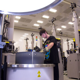
At the RE+ 2023 conference in Las Vegas, vendors from across the globe displayed their largest, thinnest, bi-facial solar modules, showcasing achievements in photovoltaic cost efficiency. Boasting wattages once unthinkable, the cost reduction juggernaut of solar has marched forward.
For those of us who have designed a solar module and performed mechanical load testing, there is one head-scratching detail that sticks-out and begs for further exploration. These massive modules come equipped with some of the smallest module frames ever seen.
The previously ubiquitous 2- by 1-meter module with a frame height of 50mm is now approximately 55% larger in surface area with frame heights as low as 30mm. How is this possible when mechanical load ratings have remained constant, and the height of a beam is of paramount importance to its strength? Those physics hold true for bridges, buildings, and even the frame of a solar module. Wind and snow loading rise proportionally with the increased surface area, but the latest, longest-ever module frames see a height reduction of ~40%, severely reducing its load-carrying capacity.
Modules are tested to various standard mechanical load tests for certification. These tests apply loads to the front-side and back-side of the module to rate them for withstanding real-world environmental conditions. The current industry standards (UL 61730-2, IEC 61730, IEC 61215-2) all generally agree on mechanical load testing procedures. Many of the modules on the conference floor advertise compliance with these standards and the industry-leading testing labs perform these certification tests with the utmost care and diligence.
While the large-format modules meet these standards in the lab, the lab is not the real-world. The field loading applied to a solar module depends on the structure on which it is mounted and the terrain of the project. The greater the wind zone, the greater the load on the module.
Less obvious is that larger tilt angles typically also increase wind loading on modules and that this varies across locations throughout the array. Picture a ship with its sails raised versus lowered during a storm. Which one has more force to project their vessel forward?
Snow can often have the opposite effect. Panels of a higher tilt angle will often shed more snow than lower tilt panels and thus be more favorable to module loading from snow. Any house roof in a northern latitude will showcase this phenomenon. The project designers must carefully check that the modules selected work with the mounting structure at every location on the project site.
Therefore, to understand the engineering gap at hand, a marriage of large-format module frame design and structural design of racking systems is key. Because module loading is dependent on the supporting structure (e.g., tilt angle, among several variables), structural vendors typically specify expected module loading in project design. Many structural vendors are good at validating that the module itself falls within the certification rating. However, is it possible that some vendors are still missing peak module loads for wind?
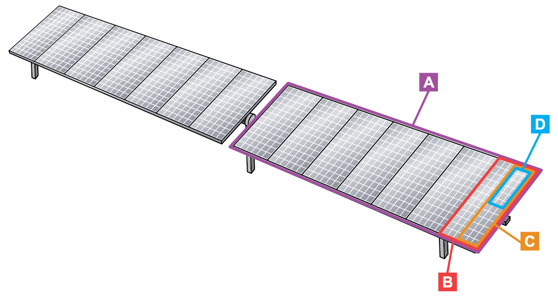
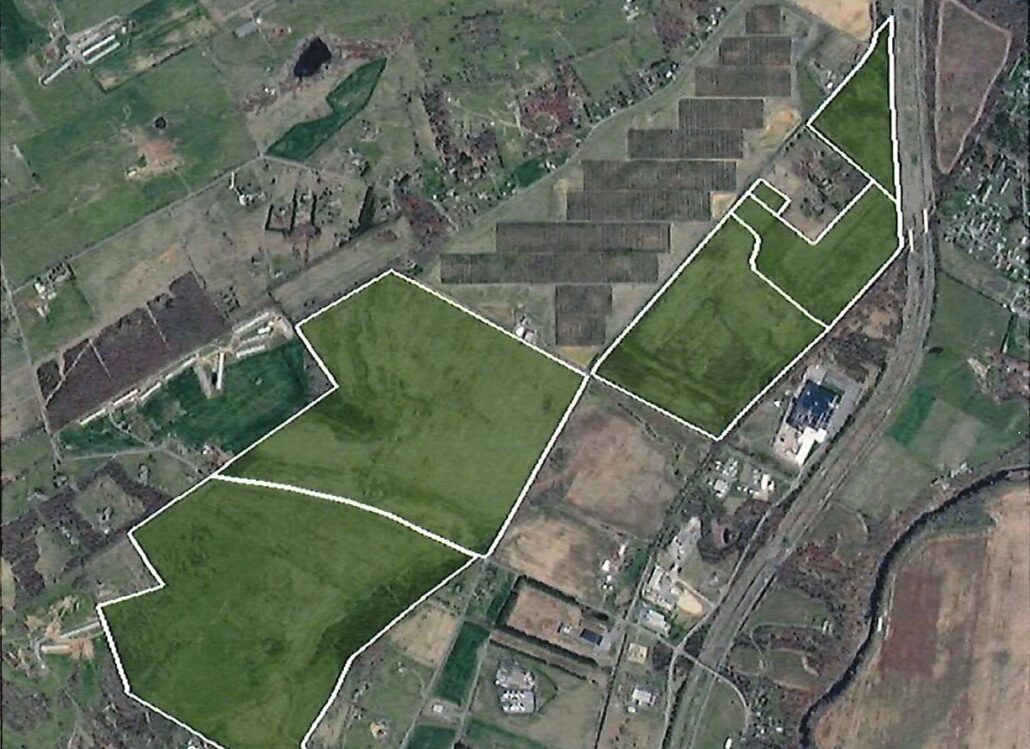
Image: Azimuth Advisory Services
A SETO-funded research project being carried out through a joint venture of the Lawrence Berkeley National Lab and UC Berkeley has determined that vendors need to look at smaller effective wind areas than the spans between foundations (not what is shown in Figure 1 A) when estimating individual module loading. PV modules can be broken if attributable areas as small as one-quarter of the module are overloaded (individual fastener level loading – D in Figure 1) and this can be shown to occur at maximum project design conditions for many projects getting installed today. While the evaluation typically carried out is around a maximum design loading, the SETO-funded research team is currently exploring how a lower, uneven cyclical loading can lead to structural failures as well.
If understated peak module wind loading has been common practice in project design for the last 15 years, then module failures should be rampant, no? In practice, older module frames have been pulling double-duty masking this oversight. Some of those module frames were designed with safety factors of 3. Today, large-format modules appear to be designed to safety factors of 1.5 based on reviews of some module manufacturers datasheets and industry standards. This allows the modules to be competitive in the downward march on cost.
When a certification laboratory tests a module to an actual 2,400 Pa of back-side loading, the maximum design pressure it is certified for is 1,600 Pa. It is critical to check if the module rating advertised is what was tested (including safety factors) or if it is what the maximum allowable design pressure is (without safety factors). 1,600 Pa of pressure on a module is approximately equal to a 72-mph wind gust for a module pressure coefficient of 3. The LBNL / UC Berkeley research team has determined that this coefficient is achievable at row ends for module tilts over 15 degrees. This is hardly a sufficient design for any project in the U.S. based on the latest ASCE 7-22 wind maps. If a designer mistakenly used 2,400Pa to be the design pressure, this would increase the allowable wind gust to 88-mph. Thus, it is important to understand what the module rating includes.
Load capacity
The market has driven module load capacity to its breaking point. This seems to be particularly the case regarding backside (wind uplift) loading. Combining legacy engineering assumptions, larger module areas, smaller module frame heights and unclear manufacturer ratings yields a recipe for failures. The goal is not to lay blame, but to understand the technical issues at hand and offer guidance on what stakeholders can do.
Here are tangible ways that developers, financiers, insurance companies, owners, asset managers, structure manufacturers and module manufacturers can manage these risks:
1. Make sure sufficient independent engineer (IE) budget and time is allocated per project (particularly smaller projects) so key details about module loading can be checked not only per project, but at every location on the project (e.g., exterior rows, corners, fasteners).
2. Structure manufacturer due diligence should confirm that:
- Clip and bolt loads for module retention use “module clip loads” (D in Figure 1) instead of average row areas (A in Figure 1) or even module-level areas (B in Figure 1). See the wind tunnel testing coefficients for more details.
- Module loading should not be assumed to be the same across the array for wind. The wind loads on modules at the end of the rows are typically higher than those on the interior. This is true for both tracking and fixed tilt systems. [See the latest SEAOC PV2 Wind Design for Loading Arrays]
- Clip/bolt loading should not be assumed to be the same at each location on the module. Loading on one half of the module is often quite different than the other. The fasteners may end up being the same design, but they should be designed to withstand the highest loading and not a lower average load distributed across the four fasteners.
- Module rails should be sized accordingly as well, with particular emphasis on exterior module rails and their appropriate rail-level area loading (C in Figure 1) and with assumptions for uneven module loading.
3. Module due diligence should confirm:
- Whether the module datasheet front-side / back-side mechanical load rating includes the test safety factor (typically 1.5). If it does not, reduce the load rating by the appropriate safety factor and confirm that the structural loading demand does not exceed that new, lower rating based upon the module wind/snow stow angle (tracker) or installation tilt angle (fixed tilt).
- That the module frame is designed to withstand the extra forces that come with uneven loading for the wind/snow stow angle (tracker) or installation tilt angle (fixed tilt) of the system.
- The mounting method exactly matches the module certification mounting method and is listed in the module installation manual. If not, the module manufacturer should be requested to issue a letter that the unapproved mounting method will uphold the warranty under the project conditions. Testing may be necessary.


The views and opinions expressed in this article are the author’s own, and do not necessarily reflect those held by pv magazine.
This content is protected by copyright and may not be reused. If you want to cooperate with us and would like to reuse some of our content, please contact: editors@pv-magazine.com.


By submitting this form you agree to pv magazine using your data for the purposes of publishing your comment.
Your personal data will only be disclosed or otherwise transmitted to third parties for the purposes of spam filtering or if this is necessary for technical maintenance of the website. Any other transfer to third parties will not take place unless this is justified on the basis of applicable data protection regulations or if pv magazine is legally obliged to do so.
You may revoke this consent at any time with effect for the future, in which case your personal data will be deleted immediately. Otherwise, your data will be deleted if pv magazine has processed your request or the purpose of data storage is fulfilled.
Further information on data privacy can be found in our Data Protection Policy.