S-5!, a manufacturer of metal roof attachment solutions with non-penetrative solutions for attaching solar systems to metal roofs, has released a three-part series of white papers examining the relationship between solar and metal roofs with the Metal Construction Association (MCA). In the first entry of this series, the two explored the advantages metal roofs inherently have in housing solar systems, from the perspective of asset lifespans and overall system lifetime costs.
In the second entry, S-5! and MCA take a deep dive into the common types of mounting systems for metal roofs, and the associated risks, pros, and cons of each.
Before mounting is even considered, installers must recognize and identify a roof’s solar zone, which is the roof area most appropriate for solar, determined by sun angle, roof obstructions, shading effects, etc. Power production efficiencies and overall system value are maximized with slopes closest to the optimal sun angle, which is south-facing for southern-hemisphere installations, and north-facing for northern-hemisphere installations.
For clarity, all hypothetical installations from the paper and referenced in this article will be southern-hemisphere installations.
Once an area has been identified, then it’s time to consider mounting.
The authors outline that the most common mounting layouts are flush or tilted, with both of those configurations leaving a roughly four-inch gap between the module and roof surface for optimal airflow and cell cooling. Adding to this, the authors also outline that falling module prices in the 2010s led to a bit of a revolution in ideal mounting configurations.
When modules were more expensive and less efficient, achieving optimal sun angle with added mounting costs was financially sound within cost recovery calculations. Now that module costs have fallen dramatically, current trends favor low-cost, flush-mounted systems that facilitate additional module installation, resulting in higher power density, in terms of watts/square foot, and less severe structural impact.
According to the report, flush-mounted systems are commonly used on metal roofs with slopes as low as 2º. And while these “near-flat” modules don’t achieve the energy density of modules positioned at the optimal sun angle, the reduction in energy production may be as little as 5% in southern areas or as high as 12% in northern areas.
these near-flat installation strategy also allows north-facing roof areas to carry arrays with power production only a few percent lower than their south-facing counterparts, making flush-mounted systems a contender for the best life-cycle cost on large, commercial low-slope roofs, particularly in southern areas of the U.S.
Rail mounted vs. direct-attach
Within flush-mounting, the installation can either be installed above the rails or ribs of the metal roof, in a configuration known as rail mounted, or directly to the rails/ribs, in a configuration known as direct-attached.
In a rail mounted configuration, the rail allows neighboring modules to be within an inch or less of each other, sometimes maximizing power density. Because the racking system is above the rails, the gap between the module and roof surface is usually seven to nine inches, allowing for extra space for optimizers and rapid shutdown equipment.
Overheating rapid shutdown equipment has been hypothesized as a cause of some rooftop solar installation fire events in the past, but the data to support such claims is incomplete, so that’s a story for another day.
While such a method generally leads to low wind loads on the system and roof, snow, ice, and debris may accumulate under the module, so periodic inspection and preventative maintenance is advised by the authors. Snow loads can create a whole host of issues, so extra consideration is recommended when planning an installation in snow-prone areas.
In direct-attach installations, since the mounting systems are attached directly to the seams or rails of the roof, the gap between the module and roof surface is usually smaller, at around five inches.
In terms of positives, such an approach can provide a more uniform load distribution to the roof and/or roof structure, with the authors stating that an such an approach could add as little as 15% of the weight that would be added to the roof in a railed approach. This approach can, however, take up more space than rail-mounted, and may not be optimal for those with limited solar zones.
Considerations for tilted modules
Using a tilted mounting system improves or maximizes module-level energy density, at the cost of an increase in the initial materials cost and added collateral dead load of those materials to the roof. Collateral dead load refers to the self-weight of permanently installed materials attached to the roof or supporting structure with the exact location unknown at the time of design.
Tilted systems also increase the wind and snow loads that a system and roof are subject to. Many times these additional loads show up outside of the loads that the roof was designed to withstand at installation, and can put a significant amount of stress on the roof as a result.
Regardless of chosen mounting configuration, PV arrays that are not properly designed and installed can become airborne during a wind event and pose a serious threat of injury, personal and property damage and present a life-safety issue.
In the next installment of the comparison series, S-5! and MCA expound on various metal roof types and code and standard requirements that cover the design, testing, manufacturing, and certifications that accompany the PV mounting system.
This content is protected by copyright and may not be reused. If you want to cooperate with us and would like to reuse some of our content, please contact: editors@pv-magazine.com.


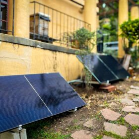


I could not agree more. We own two rooftop systems like this since several years and are very satisfied with the results. This is the perfect day to go for DIY self installers who want to save money.