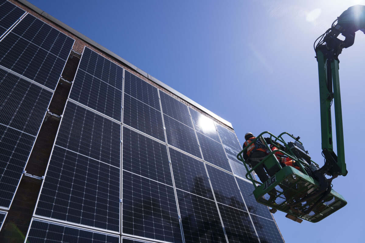
Module level power electronics (MLPE) are becoming increasingly popular in commercial rooftop and ground mount solar installations due to their ability to improve return on investment (ROI) through a combination of factors: increased energy production, greater design flexibility, and lower O&M costs. The following are three common questions asked by installers when designing or installing power optimizer MLPE systems for commercial projects.
What is the best power optimizer-to-module ratio for my project?
When designing a MLPE system, it is important to determine the level of optimization required for each project. This should be based on several factors: available roof space, level of shading, and cost.
The two most popular configurations are:
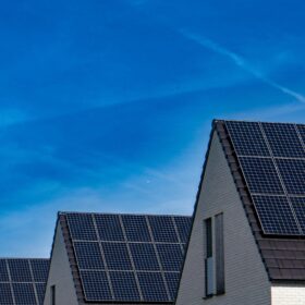
- 1:1 ratio – In this configuration, one power optimizer is attached to each module. This ratio is commonly favoured for residential installations due to space limitations and other challenges that can limit energy production, e.g., the roof has different pitches or orientations, or there is shading from nearby trees. In this scenario, a high level of optimization is required to squeeze every watt of energy from the array.
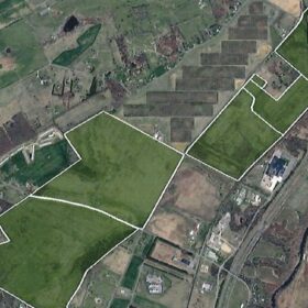
- 2:1 ratio – As installation size increases, equipment cost becomes a more important factor. Typically, commercial installations have large, flat roofs and fewer obstructions that can cause shading. In this scenario, a 2:1 ratio (two modules to one power optimizer) is generally favoured, as it provides sufficient optimization and increased energy production, while also reducing BoS components and operational costs.
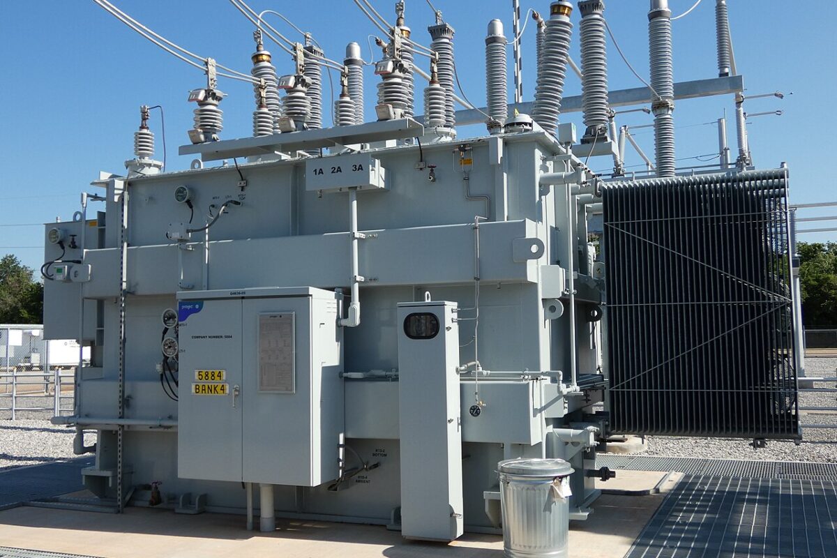
Oversizing DC/AC ratio: how much is too much?
It is a fact of life that PV modules do not consistently perform at their nominal output rating. Module output power is affected by the weather, the sun’s position during the day/different seasons, local site conditions, and array orientation. In addition, module output power may decrease due to aging, soiling and shade. Using MLPE in your project maximizes power production in all scenarios, and can improve system ROI.
Oversizing the array (in comparison to the inverter’s AC power) also helps to increase energy production. This trend became popular when PV module price levels started to fall. Producing more DC power than the inverter can turn into AC energy means the system will produce peak power for longer on sunny days, and it increases the probability that it will produce maximum power in low-light conditions.
However, too much oversizing may negatively affect plant production, resulting in a longer payback period. This is because inverters are designed to generate output power up to a maximum AC power that cannot be exceeded, and they limit (clip) the power when the actual produced DC power is higher than the inverter can output. Added to this, as oversizing causes the inverter to operate at high power for longer periods, it can also reduce the inverter’s lifetime if its oversizing capacity is not sufficient.
Inverter oversizing capacity can range considerably from 135% to 200%, depending on the brand or model of the inverter. Therefore, it is essential to check the manufacturer’s information to ensure you keep oversizing within recommended limits.
How can I avoid PV connector issues?
PV connectors are a crucial component of any solar system. However, if not installed properly during installation, there may be future consequences. Below are three common connector-related errors that can occur during installation. The good news is these can be easily avoided with a little know-how.
- Failing to properly close connectors – When installing connectors, it is important to make sure they are seated properly, as failure to do so can cause arc faults. When making a connection, ensure there is an audible click, and give both connectors a firm tug. This will let you know the connectors are securely fastened.
- Using different brands of connectors in the same install – Many module manufacturers produce their own connectors. However, this can lead to situations where installers inter-mate different brands of connectors, not realizing this is not NEC-code compliant. While different connectors may fit together initially, over time they might not work well together. One connector could corrode, or there may be a mechanical mismatch that no one sees, and so it heats up, potentially causing a problem that could become an arc fault in the future. The best way to safeguard against this is to ensure that only one brand of connector is used in each installation. If this is not possible, make sure all of connectors used are UL listed to ensure compatibility.
- Improper Crimping – When installing connectors, be sure to follow the manufacturer’s instructions that specify allowable wire types and strand counts, as well as the crimping tools required to maintain the integrity of the crimped connection.

Kleber Facchini has more than 15 years’ experience in electrical engineering, applications and product management in the renewables and utility equipment industry. As director of technical marketing, commercial & utility for SolarEdge North America, he is responsible for conceiving, defining, and launching all related products across the continent. He also oversees the applications engineering team, which works directly with SolarEdge’s installer partners.
The views and opinions expressed in this article are the author’s own, and do not necessarily reflect those held by pv magazine.
This content is protected by copyright and may not be reused. If you want to cooperate with us and would like to reuse some of our content, please contact: editors@pv-magazine.com.


By submitting this form you agree to pv magazine using your data for the purposes of publishing your comment.
Your personal data will only be disclosed or otherwise transmitted to third parties for the purposes of spam filtering or if this is necessary for technical maintenance of the website. Any other transfer to third parties will not take place unless this is justified on the basis of applicable data protection regulations or if pv magazine is legally obliged to do so.
You may revoke this consent at any time with effect for the future, in which case your personal data will be deleted immediately. Otherwise, your data will be deleted if pv magazine has processed your request or the purpose of data storage is fulfilled.
Further information on data privacy can be found in our Data Protection Policy.