This article is the third in a series which will discuss specific system reliability issues seen in North American systems (the first two articles can be read here and here). Each article focuses on a specific failure mode, giving an overview and examples of defect presentation. A longer summary article diving into a broader industry context and defect prevalence will follow this series.
By Dr. Rob Andrews and Kristine Sinclair (Heliolytics) and Bindhu Raghuraman (DNV GL)
Hot-spots in PV modules represents a broad defect type, with many presentations and underlying causes, with two examples shown in Figure 1.
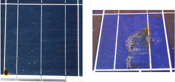
DNV GL and DuPont
Defect severity and therefore remediation actions also vary widely as a result. Here we’ll consider three broad categories that cause hot-spots. This category order also roughly follows an increasing effort of investigation and remediation, and therefore source of concern for owners and operators.
- Shading/soiling: overhead objects (ex. trees, poles, etc.), vegetation overgrowth, surface fouling, foreign objects on surface
- Mechanical damage: broken glass, broken/bent frame, collisions of modules with each other or other objects, improper fixturing
- Internal module failures: cell material defects (ex. shunts, high series resistance, etc.), cell cracks, local de-lamination, poor solder joints
The effects of shading and soiling can be mitigated during the system design phase. A detailed study can be performed to determine the effects of trees, poles, or other objects that may shade the modules throughout the day and throughout the year. Soiling can be mitigated with periodic maintenance of the system. A study of the environment where the modules are proposed to be installed can be performed and a maintenance schedule designed accordingly. If shading cannot be avoided, module-level smart electronics may be considered to mitigate risks.
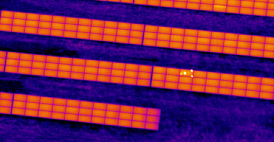
Mechanical damage to panels can also vary widely in terms of cause for concern, typically in proportion to how much of the site is affected (see Figure 2 for example image). Numerous broken modules can be for example due to a weather event such as hail or extreme winds, and would likely correspond to an insurance claim. To mitigate such risks, the environmental study proposed above can be extended to help choose the right module for the installation site. For example, if the study determines that location is prone to high winds and hail storms, modules that have been tested extensively to withstand such conditions can be selected. Either the manufacturer or an independent test lab can design test programs to suit a particular application.
Internal module failure can be caused by module handling during installation or transportation, improper fixturing/clamping, or racking issues. These mechanical issues can cause cracks and microcracks in modules, which may not initially cause performance losses or hot spots, however over long-term thermal cycling these faults will increase in severity. Therefore, a thorough commissioning process including full-site IR inspection and sampled EL is important to identify these risk factors early. Electroluminescence imaging (EL) can identify cell damage before it evolves into hot spots, while IR offers a fast and cost-effective method for detection of more severe defects across the full site, where a concentration of hot spots can indicate more widespread cell damage. Figure 2 gives an example IR image showing a module presenting with hot-spots on a utility-scale site.

Heliolytics
When not extensive across the site and not high enough temperature to be a safety concern, hot-spots due to internal module failures may not be cause for much concern; performance is typically not greatly affected, and the only action may be monitoring defect evolution during annual Preventative Maintenance activities. However, if a significant percentage of modules are exhibiting a systematic presentation of hot-spots, this can be indicative of a serial defect and an associated warranty claim (see Figure 3).
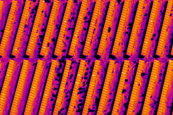
Heliolytics
Risks of design and process issues during cell and module manufacturing can be mitigated with laboratory and field testing before installation. Test programs that detect systemic manufacturing defects by testing modules from each production batch are also available to detect problems related to cell damage. Once installed, a robust O&M plan allows for early detection in order to minimize safety and revenue risks.
Interested in quality issues? Be sure to join pv magazine for our Quality Roundtable at the Solar Power International trade show on September 12. More information and registration can be found here.
This content is protected by copyright and may not be reused. If you want to cooperate with us and would like to reuse some of our content, please contact: editors@pv-magazine.com.


By submitting this form you agree to pv magazine using your data for the purposes of publishing your comment.
Your personal data will only be disclosed or otherwise transmitted to third parties for the purposes of spam filtering or if this is necessary for technical maintenance of the website. Any other transfer to third parties will not take place unless this is justified on the basis of applicable data protection regulations or if pv magazine is legally obliged to do so.
You may revoke this consent at any time with effect for the future, in which case your personal data will be deleted immediately. Otherwise, your data will be deleted if pv magazine has processed your request or the purpose of data storage is fulfilled.
Further information on data privacy can be found in our Data Protection Policy.