
705.13: Another Option for Interconnection Section
705.13 has been renamed Power Control Systems (it used to be EMS, but hey EMS has its own Article!), and it now provides a game-changer for PV and storage interconnections: the use of multisource PCS. You could call it “super-sizing” source connections, or consider it the answer to “how do you connect storage to a panelboard that’s already maxed out with PV?”
A PCS can be set to actively limit the current and loading on a busbar(s) and/or conductor(s), functionality referred to as its “control setting” or “setpoint.” This enables connections of power sources with more current than what 705.12 would traditionally allow for load-side connections. Why? Because a listed PCS guarantees safety by actively controlling power source current, ensuring the equipment and/or conductor ratings are never exceeded.
The benefit is obvious: cost savings and increased utilization of electrical infrastructure. More generation or storage can be added to existing panelboards without expensive upgrades, as conductors and overcurrent protective devices (OCPDs) are sized based on the PCS setpoint, not the aggregate source(s) output.
Be sure to review the Informational Notes in 705.13 – they provide good detail; point to UL 3141 and UL 1741; and state that a PCS may include connection to an electric power production and distribution network (typically the grid), which by extension means it doesn’t have to. Remember the grid may be the primary power source, but it also may not!
120.7: Smarter Load Calculations
The changes to 120.7 (also named Power Control Systems, and formerly located and briefly addressed in 220.70) are profound. The allowance to use a PCS setpoint for load calculations is now a general provision, applying not just to feeders and services, but to branch circuits as well.
There are several requirements when basing load calculations on the presence of a PCS:
- It has to comply with Part II of Article 130 (also called Power Control Systems), which addresses general PCS requirements (several of which are essentially manufacturer-facing). These include what must happen in a malfunction (it must transition to a controlled state that prevents overload); access to adjustable settings; and marking and documentation.
- You have to know what you are doing! The PCS control setting has to be determined by a qualified person, and cannot be any more than 80 percent of the rating of the OCPD for the circuit the PCS is monitoring for overload control
- Monitored loads (loads for which a PCS can measure current flow) may be controlled by the PCS (the PCS can limit current); uncontrolled by the PCS (the PCS cannot limit current); or a combination, and it matters.
120.7(C) spells out how to calculate the load on branch circuits, feeders, or services with PCS: it is the sum of controlled loads + the sum of noncontrolled loads. Noncontrolled loads are “regular” loads, and as such the “regular” Article 120 calculations apply. If there are only controlled loads, the value for load calculations is simply the PCS control setting.
If the PCS monitors both controlled and noncontrolled loads, the load calc value for the controlled portion must be its “minimum operating current.” Minimum operating current is not defined in the NEC, though an Informational Note in 120.7(C)(1) “clarifies” minimum operating current as a value greater than or equal to zero, representing the minimum current of the controlled loads. This means you’ll have to get data from the equipment manufacturer to quantify this value. For example, an EV charger might only have the capability to ramp down to a minimum of 10 amps; this would be the minimum operating current.
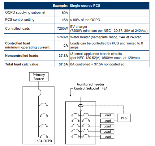
This 37.5A value can be used for the service and feeder load calculations. This could be helpful if you are doing load calcs for a service, or if this feeder is to an accessory dwelling unit and the goal is to avoid a service upgrade. However – and this is a critical safety point – the controlled feeder conductor must be sized based on the 60A OCPD supplying it, not the 37.5A load calc value.
This is very different from traditional methods! Remember that regardless of these rules and their application, a logical analysis of the end-user experience and the loads they want to operate simultaneously is important: the setpoint of the PCS should be sufficient for the loads to be served.
As always with the NEC, following 120.7 allowances won’t be unsafe but it may not be “efficient, convenient, or adequate for good service or future expansion of electrical use.”
702.4(A)(3): “Right-Sizing” Optional Standby Systems
The addition of 702.4(A)(3) directly addresses a long-standing problem for battery-backup systems: using traditional load calcs to determine the minimum required capacity for a “backed-up loads panel” could result in over-sized power sources. Previous options for optional standby system capacity were based on whether the system had manual and nonautomatic connection of load (putting the responsibility on the end-user), or if there was automatic load connection (in which case the system either had to be sized for the full load, or have an EMS to limit load to the capacity of the standby source).
702.4(A)(3) is an allowance specifically for multimode inverter-based systems in one- and two-family dwellings and allows “right-sizing” a standby system by using the PCS-listed inverter to manage the loads.
The key requirements are:
- The multimode inverter must be listed as a PCS for overload control.
- The minimum inverter capacity (its rated output current) must be at least equal to the PCS control current set point.
- The inverter capacity must be greater than or equal to the load of the largest single piece of utilization equipment.
- In case of an overload shutdown, the inverter’s reconnection must be nonautomatic. This is a practical, engineered solution that finally gives installers a code-compliant path to install reasonably-sized, cost-effective backup systems.
Impacts, Benefits, and What’s Next
The impacts of these changes are immediate and far-reaching. Controlled loads and more generation can be connected to existing infrastructure, saving clients significant money on service, feeder, and panelboard upgrades. It enables “smart grid” opportunities and provides the flexibility to install systems (like battery backup) that customers want, without the unnecessary costs resulting from old calculation methods. And this is all achieved while maintaining, and perhaps increasing, safety, as these systems rely on active, real-time monitoring to provide overload protection, not just passive overcurrent protection.
The 2026 NEC laid the groundwork, but there’s still work to do.
- “Minimum operating current,” as used in 120.7(C), is undefined, putting the burden on installers and designers to get the right data for a variety of different equipment.
- While “qualified person” is defined in the NEC, 130.7(B) requires the PCS control setting be “determined by a qualified person.” The industry and AHJs will need to establish what this determination means in practice for designing and commissioning these systems.
- As with any new code language, there are potential “illogical” quirks that may only become apparent when put into practice. As an example, see the preceding sizing example on 120.7: the system is safe, but there is ambiguity related to minimum feeder ampacity that isn’t consistent with requirements elsewhere in the NEC, suggesting further refinement will happen in the 2029 code cycle.
Ultimately, the 2026 NEC has embraced a new philosophy. By formally integrating power control systems, the code recognizes that the future of electrical system design is not just about building bigger, but about building smarter. Reach out to us at Solar Tech Collective if you’re interested in staying informed and engaged on developments in codes and standards related to power control systems.
Brian Mehalic is a Senior Consultant at Solar Tech Collective, specializing in consulting and training on codes, standards, and O&M for PV, energy storage, and EV systems.
The views and opinions expressed in this article are the author’s own, and do not necessarily reflect those held by pv magazine.
This content is protected by copyright and may not be reused. If you want to cooperate with us and would like to reuse some of our content, please contact: editors@pv-magazine.com.


By submitting this form you agree to pv magazine using your data for the purposes of publishing your comment.
Your personal data will only be disclosed or otherwise transmitted to third parties for the purposes of spam filtering or if this is necessary for technical maintenance of the website. Any other transfer to third parties will not take place unless this is justified on the basis of applicable data protection regulations or if pv magazine is legally obliged to do so.
You may revoke this consent at any time with effect for the future, in which case your personal data will be deleted immediately. Otherwise, your data will be deleted if pv magazine has processed your request or the purpose of data storage is fulfilled.
Further information on data privacy can be found in our Data Protection Policy.