Aerial inspection, paired with solar-specific data models and analytical software, has become one of the fastest-growing technologies in solar plant operations and maintenance (O&M).
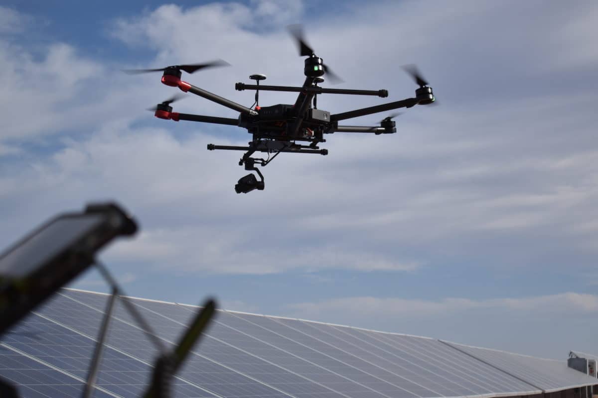
Depending on the use case, aerial inspection can be done by unmanned drone or manned aircraft, and with satellite imagery also used to assist with data model generation.

Although innovations are occurring rapidly, many solar plant O&M operators still aren’t using airborne monitoring and analysis to its full potential. When asset owners don’t take advantage of these tools, they are missing a chance to mitigate risk and optimize the health of the DC side of their system. The causes of possible plant underperformance remain underreported and insufficiently analyzed, resulting in financial returns being left on the table.
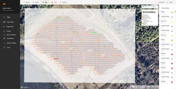
Software is used to digitize site-specific schematics and fuse the data model with and aerial-based thermography and photography. This offers a powerful holistic tool for:
- Enhancing plant performance and minimizing production loss
- Creating documentation for warranty claims and insurance
- Initiating predictive maintenance
- Predicting pre-failure anomalies
- Reducing investment risk
- Increasing worker safety.
Software enables this process to scale across the solar industry by analyzing utility-scale and commercial and industrial (C&I) datasets in bulk and standardizing the reporting process. It accurately identifies, classifies, and prioritizes all anomalies and provides the exact onsite location for efficient remediation.

While the O&M and asset management benefits of aerial inspection and data analysis are numerous and increasing, this article will focus on a few practical, boots-on-the-ground/wings in-the-air examples of improvements these new technologies have delivered.
Beyond I-V curve tracing
Solar O&M managers have traditionally relied on I-V curve tracing (current–I–and voltage–V) to offer the asset owner a broad-spectrum review of site performance at the string and combiner levels during the maintenance process. This tool is used to help determine issues such as whether there is a string offline, whether panels are failing in some sort of serial or design defect manner, or if a lightning strike or other event has caused a non-obvious production guarantee issue not detected by the plant’s monitoring system.
While both I-V curve tracing and the less-expensive voltage current inspection method can be useful in identifying some symptoms of underperformance, they also have some disadvantages.
For example, I-V curve tracing works really well to measure the degradation of individual PV panels to see if the panels are following the guaranteed production profile. But, when used as a tool to diagnose what’s going on with an entire string or multiple strings, the results are more challenging to interpret.
Because the I-V curve measures many other things besides the panels themselves, it can be difficult for a field technician to clearly determine if there is some problem that he or she should investigate. The I-V curve may look irregular, but figuring out what is behind the cause of that irregularity is not straightforward. From a training perspective, it can be hard to establish clear guidelines for what technicians should do when they see certain things and decide whether or not to investigate.
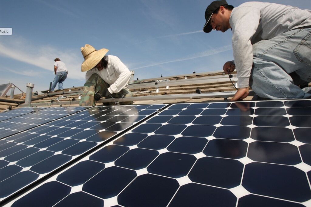
In addition, I-V curve tracing presents a safety risk. Technicians are often doing I-V curves from a combiner box, unterminating and terminating parts of the system. It’s not always easy to run all the systems when wearing all the necessary safety gear. Solar components like connectors and termination blocks were not designed to be disconnected and reconnected regularly, not multiple times a year or even once a year. Usually, these devices are locked into place, and that’s where they sit.
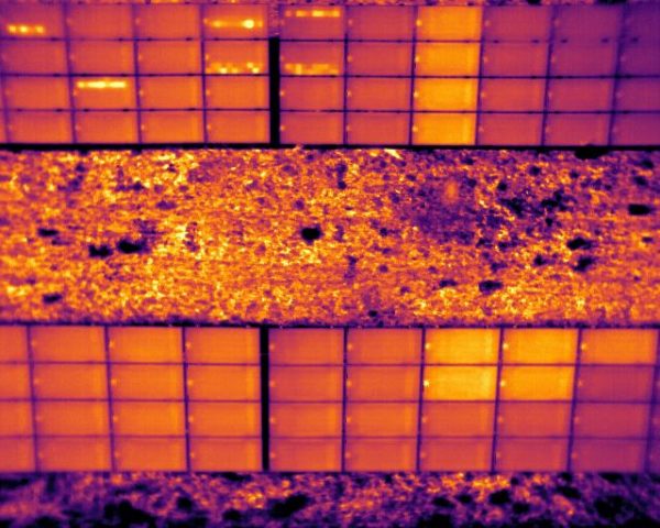
Image: Borrego
Other issues with I-V curve tracing include a lack of real-time, continuous diagnostic information leading to under-detection of defects or underperformance between inspections, as well as the additional cost of sending technicians to the work site with incomplete information or guidance to search for supposed problems.
I-V curve testing is time-consuming as well, as it takes hours for each megawatt of installed capacity. Documentation and reporting to the customer can also lack clarity and make it difficult for them to interpret and act on the findings. Put all these factors together, and I-V curves are not highly effective as a maintenance method to determine if there is an overall problem going on.
Bird’s eye view
While aerial thermography was considered experimental several years ago, it has become increasingly required by asset owners and used by operators. Most O&M contracts include the use of thermal imagery as part of the maintenance package, albeit by a ground technician using a hand scanner. This approach is cumbersome, time-consuming, and expensive. Enter aerial inspection.
Aerial thermography is quicker, more cost-effective and predictable compared to boots-on-the-ground manual inspections. It only takes hours to inspect a large PV power plant; the granular data collected down to the sub-module level provides actionable evidence of root cause issues.
Contrast this with the time- and labor-intensive interpretation of I-V curves or individual handheld thermal images that were done at different times of the day or week under changing weather conditions. The O&M and asset management teams can take the results and analysis from the eyes in the sky and identify specific work site locations that need corrective maintenance. They then can prioritize their punch list based on the impact the anomalies could have on performance. For the owner, aerial thermal images and related analyses are clear, color coded, and easy to understand.
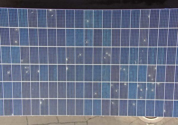
Thermography is only part of the aerial inspection story. Aircraft are also equipped with high-resolution color cameras to help stratify the actual cause of an anomaly detected by the thermographic apparatus. Cracking and internal hotspots can all look similar on thermal images; photos offer the ability to go beyond classifying the issue as merely a “hotspot” and get to the root cause of the problem.
Underpinning all of this is the use of a “digital twin,” which leverages as-built drawings to create a standardized data model that provides the intelligence of electrical relationships within the inverters and combiners of the PV system, where every panel is represented properly in terms of location and those relationships. On the ground, technicians can use smartphone or tablet apps to use the data model to quickly go to the problem areas that need attention. Additional data, such as serial numbers and vital documentation, can be associated with elements of the digital twin and shared with the appropriate counterparties.
Changes in warranty claims
One area where aerial inspection technologies have made a profound impact is warranty claims. Until recently, the prevailing attitude in the solar industry has been that if I-V curve tracing could be done on every maintenance procedure, that data would be all the documentation needed to file warranty claims.
Aerial inspection brings a clarity and relative simplicity to the warranty claims process. The integrity of the data and transparency of the aerial inspection and analysis process has made module anomalies easier to identify and prove potential warranty claims than the traditional I-V curve methods. Many OEMs are accepting aerial data on its own, without additional I-V curve information.
Aerial inspection hardware and software offers asset owners and O&M providers a way to communicate clearly and quantitatively with each other. A digitized, audit-friendly platform provides detailed classification and location of anomalies, optimizing workflow and system performance, reducing labor costs by effectively deploying field technicians and allocating resources, and improving worker safety.
Nikhil Vadhavkar is CEO and cofounder of Raptor Maps. Joe Thorpe is senior VP of O&M for Borrego.
The views and opinions expressed in this article are the author’s own, and do not necessarily reflect those held by pv magazine.
This content is protected by copyright and may not be reused. If you want to cooperate with us and would like to reuse some of our content, please contact: editors@pv-magazine.com.




By submitting this form you agree to pv magazine using your data for the purposes of publishing your comment.
Your personal data will only be disclosed or otherwise transmitted to third parties for the purposes of spam filtering or if this is necessary for technical maintenance of the website. Any other transfer to third parties will not take place unless this is justified on the basis of applicable data protection regulations or if pv magazine is legally obliged to do so.
You may revoke this consent at any time with effect for the future, in which case your personal data will be deleted immediately. Otherwise, your data will be deleted if pv magazine has processed your request or the purpose of data storage is fulfilled.
Further information on data privacy can be found in our Data Protection Policy.